
A compact folding phone stand designed to travel flat, hold a phone with a PopWallet, and allow charging during use.
Designed to Open Up -- and Pack Down
After leaving my usual phone stand in Pittsburgh, I needed a replacement to use during the summer in San Francisco. I wanted something sturdy enough for everyday use but much easier to store and transport than a conventional rigid stand.
The design also needed to accommodate the way I actually use my phone. It had to support the added thickness of a PopWallet, keep the charging port accessible, and fold into a thin package without requiring loose hardware or extensive support material during printing.
Design Opportunity
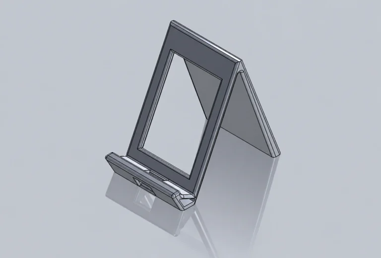
The original one-piece concept established the phone position and basic supporting form, but its enclosed geometry would have required extensive support material and could not fold for transport.
Final Design
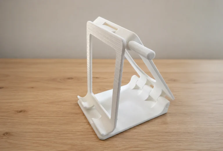
The final five-component design uses a folding structure and nested parts to support the phone at a stable viewing angle, preserve charging access, and pack down to approximately 0.3 inches thick.
PROJECT OVERVIEW
Stand By is a folding phone stand developed through eight major iterations and repeated physical testing.
The final design holds a phone with its PopWallet attached, preserves access to the charging port, and folds into a compact profile for storage or transportation. Although modeled in SolidWorks, each component required physical printing to verify fit, movement, and real-world stability.
DESIGN GOALS
Create a phone stand that:
- stands independently during use
- supports a phone with a PopWallet attached
- leaves the charging port accessible
- remains stable at the intended viewing angle
- folds into a thin, compact form
- avoids excessive support material
- uses printable joints and tolerances
- keeps the separate parts secure when stored
INITIAL CONCEPT
The initial concept used a single rigid structure with an angled rear support and an integrated phone ledge.
Although the form could hold the phone, reviewing the model in SolidWorks revealed that its enclosed geometry and printing orientation would require extensive supports. Rather than spending time and filament on a concept I already knew I would replace, I moved toward a modular folding design.
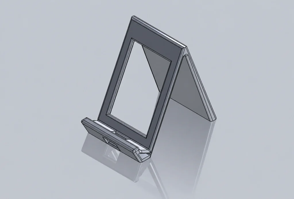
Initial concept: A rigid one-piece stand provided the basic supporting geometry but was not optimized for portability or FDM manufacturing.
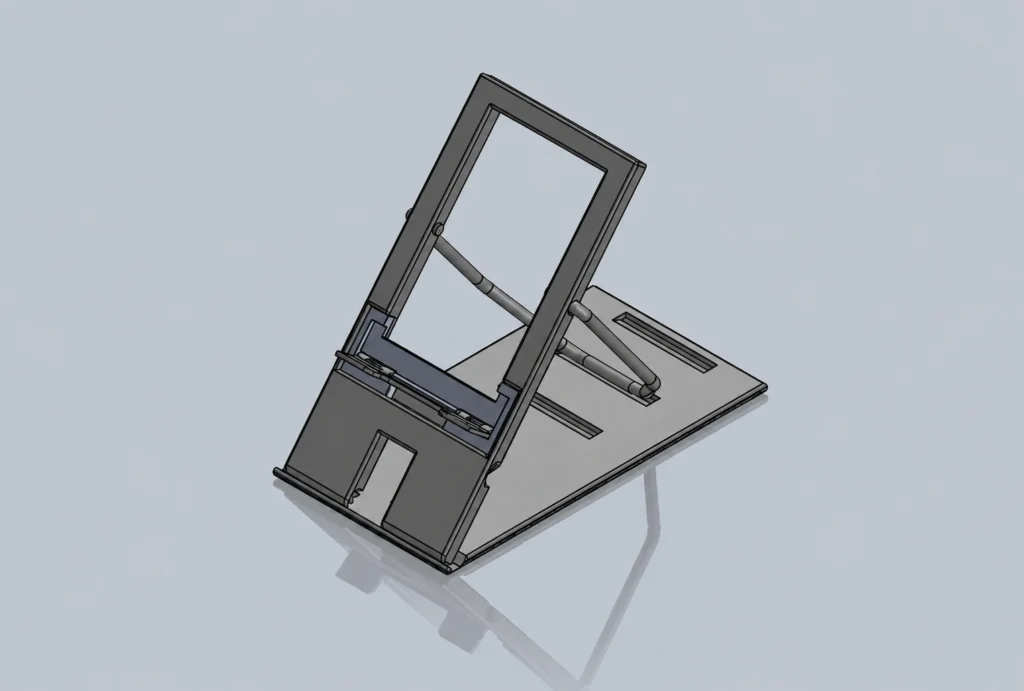
Revised architecture: Version 3 introduced the multi-part, friction-supported structure that became the foundation of the final design.
The Problem
The design needed to meet several requirements that competed with one another.
A stand thick enough to remain stable could become inconvenient to transport. A folding mechanism could reduce its size but introduce weak joints, loose parts, or unreliable viewing angles. The phone ledge also needed to support the device without blocking the charging port, while the rear structure had to accommodate the added thickness of a PopWallet.
The largest technical challenge therefore was not simply creating a stand that folded. It was developing a mechanism that could move freely during assembly, remain stable when open, and nest securely when closed.
Early Prototypes: Versions 1-2
Version 1 -- Printability Review
The first design was modeled as one rigid piece. It provided the basic phone-support geometry but would have required a large amount of support material because of its angled and enclosed surfaces.
I chose not to print this version. Evaluating its manufacturability in CAD allowed me to avoid spending filament and print time on a direction that did not meet the project's portability or production goals.
Version 2 -- Unstable Hinges
Version 2 divided the stand into three pieces connected by two hinges. This reduced the need for supports and allowed the assembly to fold more compactly.
However, the hinges did not provide enough resistance to hold the frame at the desired viewing angle. When opened, the stand gradually rotated forward under its own weight.
Design Iteration: Versions 3-5
Structure
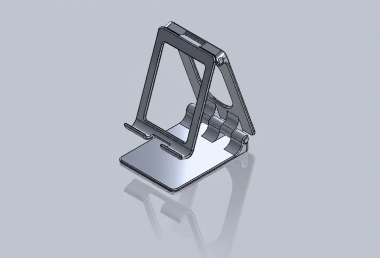
Version 3 introduced the basic arrangement used in the final product: a frame, rear support, connecting rod, table stand, and rotating phone-support component.
Rather than depending on two loose hinges to define the viewing angle, the redesigned assembly used the relationship between the frame, rod, and table stand to create a more stable structure.
Geometry
During Version 4, I adjusted component thicknesses, support angles, and clearances to improve the viewing position and reduce interference between the folding parts.
Thest changes were evaluated through repeated printing because the SolidWorks assembly did not always reveal whether parts could physically move past one another or nest as expected.
Hinge Mechanism
Versions 4 and 5 focused heavily on the phone-support hinge.
The hinge consists of two separately modeled parts designed to print together in their assembled position. Early clearances were too small for FDM printing, causing the parts to fuse instead of rotating.
To test the mechanism more efficiently, I isolated the hinge from the rest of the stand and printed in independetly. Printing it upright on its side produced the most reliable result.
By Version 5, I had finalized the hinge geometry, mating dimensions, and printable clearance needed to preserve movement wihtout allowing the parts to separate.
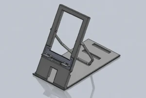
Version 3
The design transitioned to a multi-part structure that used component geometry and friction to support the frame rather than relying on loose hinges.
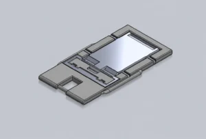
Version 4
The full-length table stand was replaced with a smaller support that fit inside the PopWallet cutout, reducing the folded size and establishing the compact nesting strategy used in later versions.
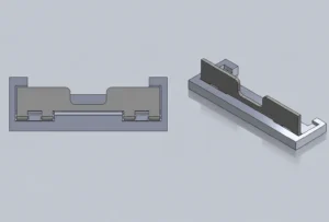
Version 5
The two-part hinge geometry and printable clearances were finalized after earlier prototypes fused during printing.
Compact Integration: Versions 6-8
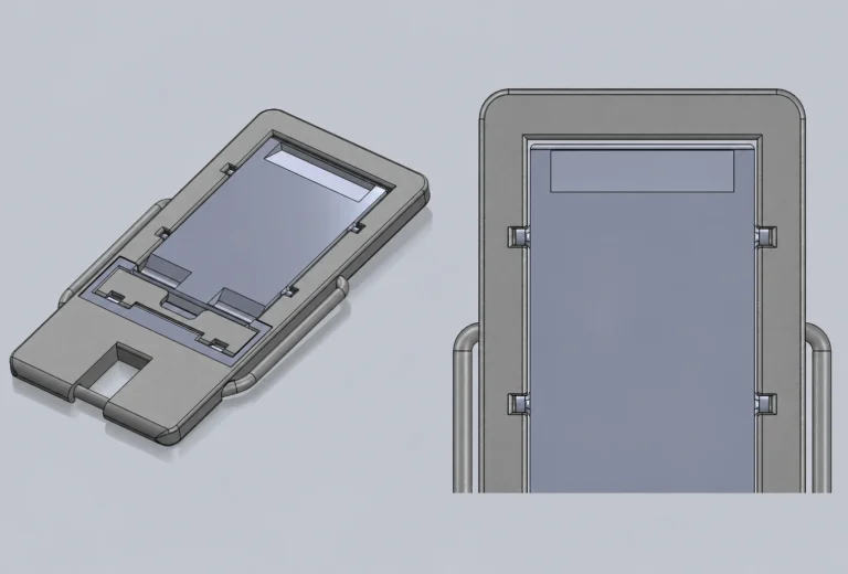
By Version 6, the overall folding architecture was already established. The remaining iterations focused on making the nested components fit more securely and improving how the separate parts were retained when the stand was folded.
Version 6 -- Nesting the Table Stand
Version 6 continued refining the smaller table stand introduced in Version 4. Its dimensions and interface with the frame were adjusted to improve how it nested inside the PopWallet cutout while maintaining the fixed viewing angle.
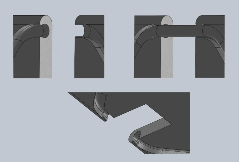
Version 7 -- Improving Retention
Version 7 further refined the table stand so it seated more securely within the frame and reduced looseness in the folded assembly.
Version 8 -- Final Integration
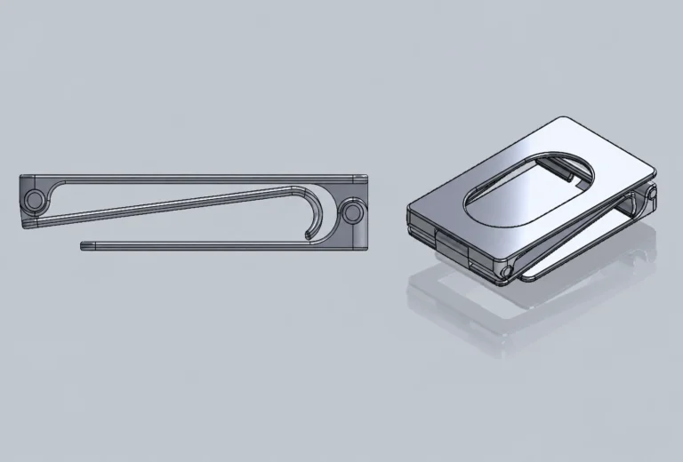
The final iteration focused on keeping the separate components organized during storage. I finalized the frame clip used to retain the support rod and made the final adjustments to the table stand fit.
Together, these changes allowed the stand to fold into an approximately 0.3-inch-thick package while keeping the components nested and contained.
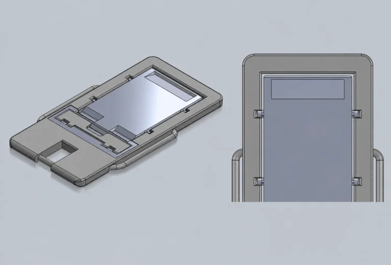
Version 6
The compact table stand was further refined to improve its fit within the PopWallet cutout and preserve the thin folded profile.
Version 7
Interface geometry was adjusted to reduce looseness and help the table stand seat more securely in the folded assembly.
Version 8
The final frame incorporated the retaining clip for the support rod and the final table-stand fit adjustments.
Final Assembly
The final stand consists of five modeled components:
- main frame
- support rod
- table stand
- rotating phone ledge
- hinge body
The phone ledge and hinge body are printed together as a two-part moving hinge subassembly. The remaining components attach mechanically and fold into the frame for storage.
Each component serves more than one purpose. The frame supports the phone and retains the rod; the table stand stabilizes the assembly and nests inside the PopWallet opening; and the hinge allows the ledge to fold flat while preserving charging access.
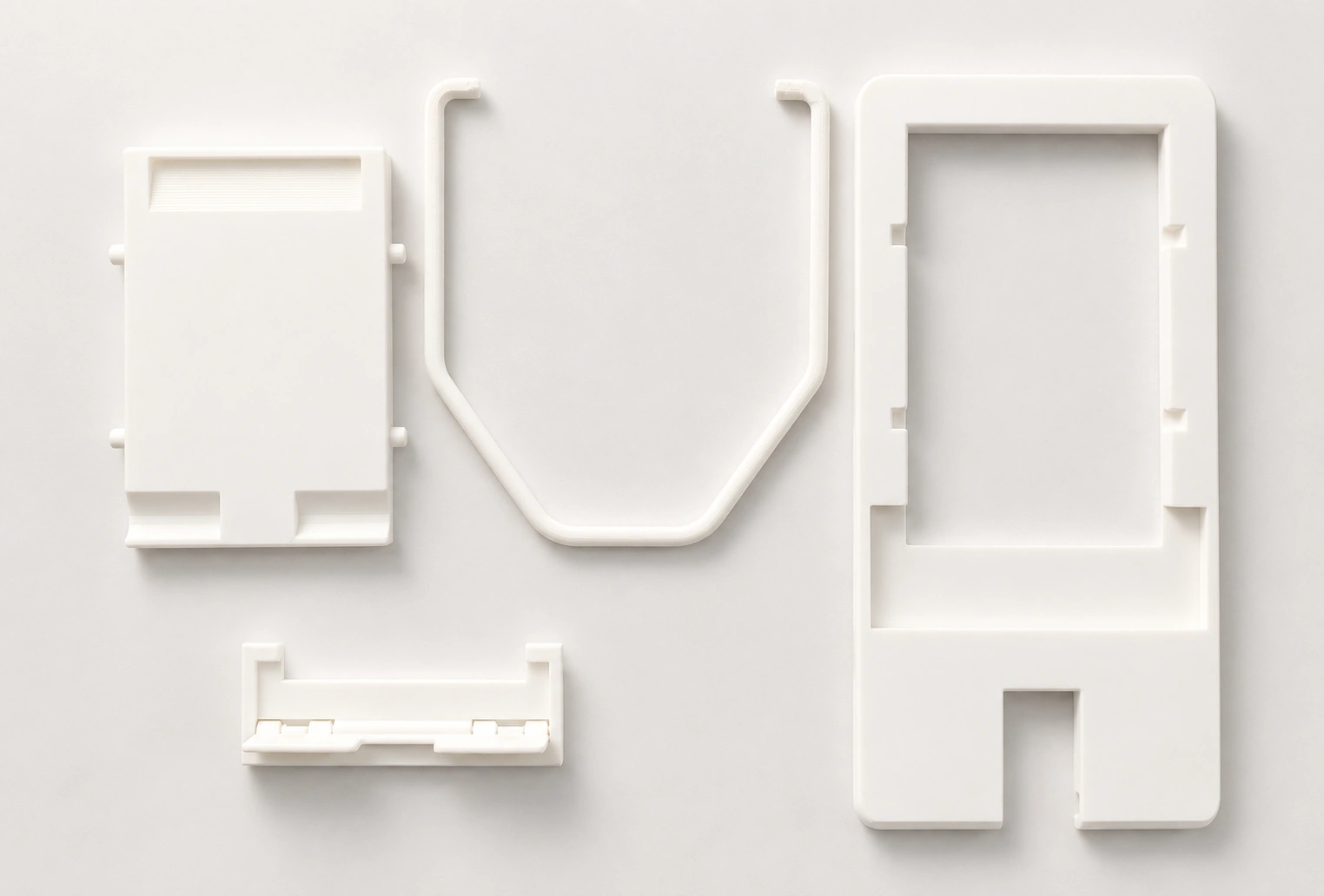
Final five-component system. Two separately
modeled hinge parts are printed together
as one moving assembly.
Final Design
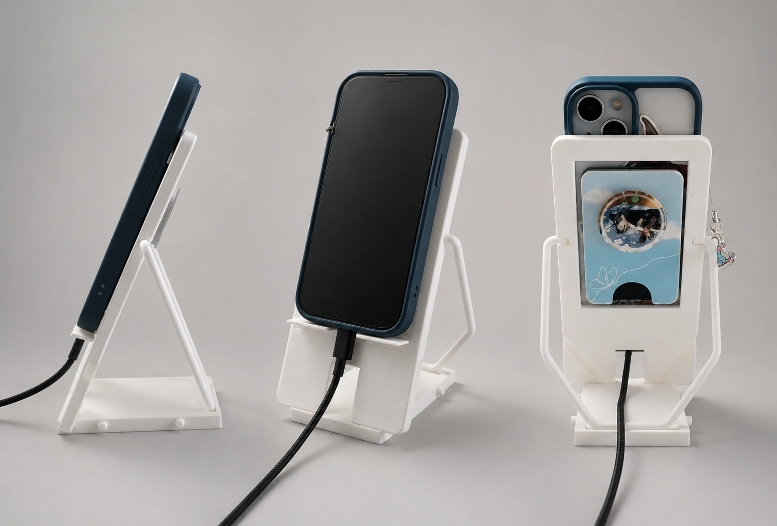
Stand By supports a phone at a stable, fixed viewing angle while preserving space for both the PopWallet and charging cable.
When no longer needed, the frame, rod, table stand, and hinge components fold and nest into a compact package. The final design replaces the support-heavy rigid concept with a portable mechanism created specifically for FDM manufacturing.
The finished prototype meets the primary functional requirements, although the single viewing angle reflects a deliberate tradeoff made to achieve a thinner and more reliable folded configuration.
Results
The final prototype successfully:
- stands independently during use
- supports the phone at a stable viewing angle
- accommodates the attached PopWallet
- preserves access to the charging port
- folds into an approximately 0.3-inch-thick profile
- uses a functional two-part printed hinge
- retains the support rod within the folded assembly
- avoids the extensive supports required by the original concept
The final mechanism demonstrated that compact storage and usable stability could be achieved through coordinated part geometry rather than a bulky fixed structure.
Future Improvements
- Increase the strength and rigidity of the support rod.
-Improve the rod clip so it holds the component more securely over repeated use.
- Refine the table stand’s appearance and integrate it more cleanly with the frame.
- Reduce overall weight through thinner sections or an alternative material.
- Explore stronger or lighter filaments while preserving hinge movement.
- Add anti-slip feet or surface texture for smoother tables.
- Investigate an adjustable-angle mechanism without significantly increasing folded thickness.
- Improve exterior print quality and reduce visible support or layer artifacts.
- Test repeated folding cycles to evaluate long-term wear in the hinge and clips.
Key Takeaways
Stand By reinforced that a working CAD assembly does not guarantee a working physical product.
SolidWorks was useful for defining the mechanism and checking nominal relationships, but physical prototypes revealed fused hinges, interference, weak retention, unstable joints, and nesting problems that were not always obvious digitally. Reprinting individual parts rather than the full assembly allowed me to isolate each issue and refine the design more efficiently.
The project also strengthened my understanding of designing specifically for FDM manufacturing. Hinge clearance, print orientation, support requirements, layer direction, and material behavior all influenced the final geometry.
Most importantly, I learned to make deliberate tradeoffs between competing requirements. Limiting the stand to one viewing angle allowed me to produce a thinner, more stable, and more portable final design that better addressed the original problem.