An accessible bicycle brake retrofit that replaces a high-force finger squeeze with a lower-effort horizontal push.
Rethinking the Braking Motion
Standard bicycle brakes rely on a finger-squeezing motion that can be difficult for riders with limited grip strength or hand mobility. Rather than simply making the existing lever larger, our team explored how the braking motion itself could be redesigned.
The final retrofit replaces the traditional squeeze with a horizontal push. A compact mechanical system transfers that input through a geartrain to actuate the existing brake, reducing the force required from the rider while preserving the bicycle's original braking mechanism.
Design Opportunity
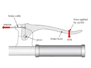
Traditional bicycle brakes require users to repeatedly squeeze a lever with their fingers, creating a barrier for riders with reduced grip strength or hand mobility.
Final Design
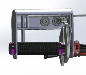
The final retrofit converts a horizontal hand push into braking force through a compact geartrain and claw mechanism, reducing the effort required to activate the existing brake.
PROJECT OVERVIEW
Take a Brake is a mechanical retrofit designed to make bicycle braking more accessible for riders who struggle with traditional squeeze levers.
The system uses a horizontal input lever, geartrain, and claw actuators to operate the existing bicycle brake. The design preserves a fully mechanical braking system while changing both the direction and magnitude of the user’s input force.
DESIGN GOALS
Create a brake retrofit that:
- reduces the hand force required to brake
- avoids reliance on finger grip strength
- uses a more accessible pushing motion
- maintains reliable braking performance
- integrates with an existing bicycle brake
- remains entirely mechanical
- maintains structural stiffness under load
- fits into a compact handlebar-mounted assembly
INITIAL CONCEPT
The first concept focused on reducing the range of motion required to activate the brake by rotating the handle orientation.
Although this approach addressed motion range, it still relied on finger strength and added unnecessary complexity. Feedback during the first design review pushed the team to reconsider the problem more fundamentally: instead of modifying the existing squeeze motion, the mechanism should change the type of motion required to brake.
That pivot led to three core design insights:
- mechanical advantage was necessary to reduce user effort
- gear alignment needed to remain controlled throughout the mechanism
-the braking system should minimize opportunities for failure by avoiding unnecessary complexity and electronics
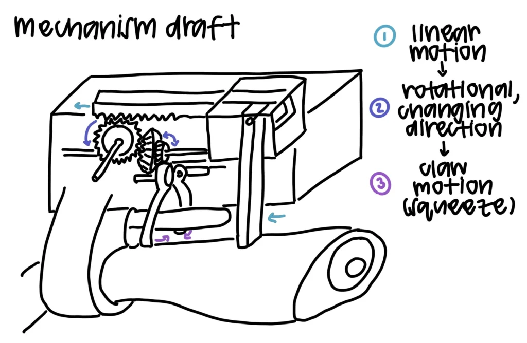
Mechanical concept: Early geartrain sketch exploring how linear hand motion could be redirected through gears to actuate the existing brake.
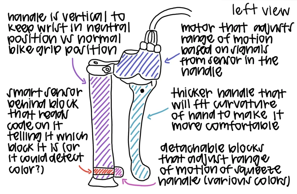
Ergonomic concept: Early handle redesign exploring a neutral wrist position, a thicker grip, and interchangeable blocks that could adjust the squeeze range for users.
The Problem
Traditional bicycle brake levers require a squeezing motion that can be difficult for riders with limited grip strength or hand mobility. The project’s user research identified requests for much lower grip force, larger ergonomic controls, and activation methods that did not depend on finger strength. Standard brakes were estimated to require roughly 35-40 N, while riders in the target group may be able to generate only 10-25 N comfortably.
The challenge was therefore larger than redesigning the shape of a brake lever. The system needed to change how the rider applied force while still generating enough output to reliably activate the existing brake.
Because braking is safety-critical, the design also needed to remain mechanically robust, maintain gear alignment, and minimize unnecessary components or failure points.
Developed Concept
After the initial rotated-handle concept was rejected, the team shifted toward a retrofit that changed the braking motion itself.
Rather than asking the rider to squeeze a lever with their fingers, the redesigned system uses a horizontal push. That input is transferred through a mechanical geartrain, allowing the design to change both the direction and magnitude of the rider’s force.
The updated concept retained the existing bicycle brake as the final braking mechanism while adding a subassembly that could provide mechanical advantage and a more accessible input motion. CAD, hand calculations, and FEA were then used to refine and evaluate the design.
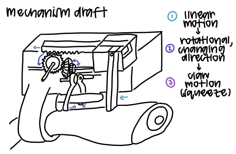
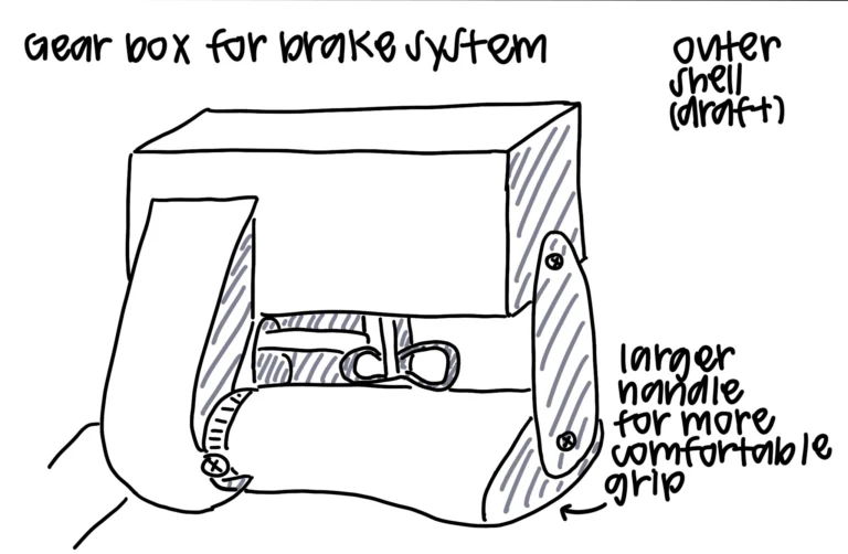
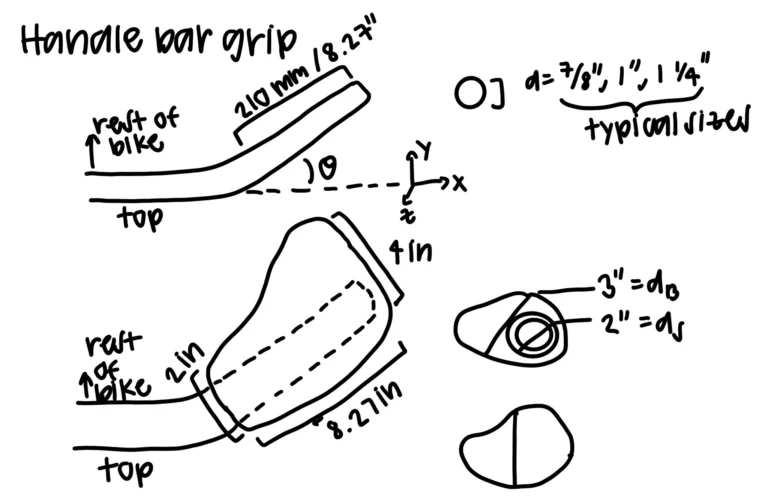
Developed concept sketches showing the horizontal input, internal geartrain, and integration with the existing bicycle brake.
How the Mechanism Works
Horizontal Input
The rider applies force through a side-to-side horizontal motion rather than squeezing a traditional brake lever.
This changes the interaction so braking relies less heavily on isolated finger grip strength and allows the rider to apply force through a larger hand movement.
Mechanical Advantage
The horizontal input drives a compact geartrain that redirects and amplifies the rider's force.
The final design uses an approximately 3:1 gear ratio, reducing an estimated 40 N braking requirement to roughly 13 N of user input.
Brake Actuation
The amplified output drives claw-shaped actuators that engage the bicycle's original brake.
This allowed the team to redesign the user interaction without replacing the entire braking system. The retrofit remains purely mechanical and contains no electrical components.
Force Transmission
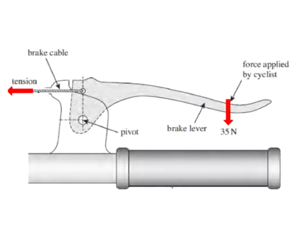
Traditional bicycle braking uses a finger squeeze to rotate the lever and pull the brake cable.
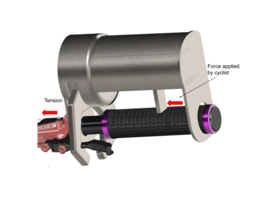
Take a Brake replaces the squeeze with a horizontal push and redirects the user's input through the retrofit mechanism.
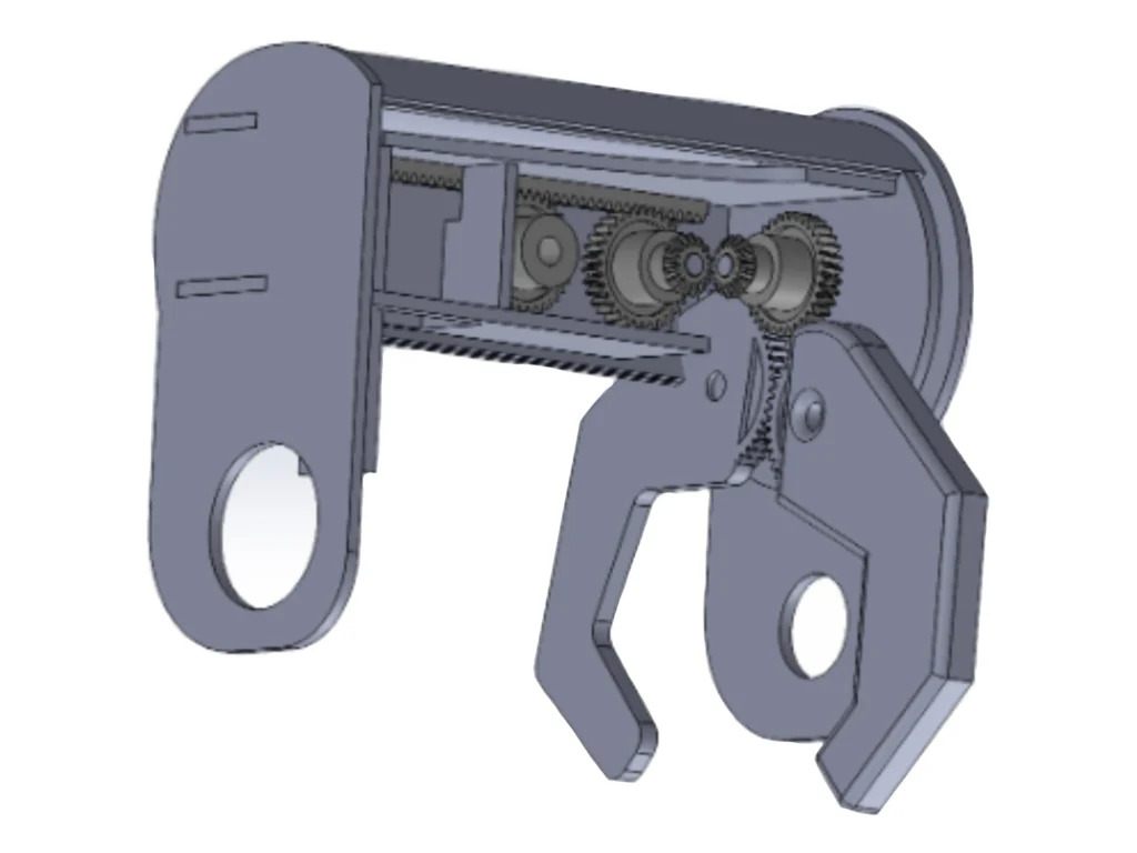
Internal geartrain and claw mechanism to transmit and amplify the rider's input.
CAD Development
Once the mechanism was established, the team developed the subassembly in CAD to package the lever, gears, housing, and claws into a compact handlebar-mounted system.
Multiple views were used to evaluate component placement and understand how the mechanism would move within the available space. The open CAD configuration exposed the internal geartrain, while the full assembly showed how the retrofit connected to the original handlebar and brake system.
The CAD model also provided the dimensions and geometry used later in the analytical stress calculations and structural validation.
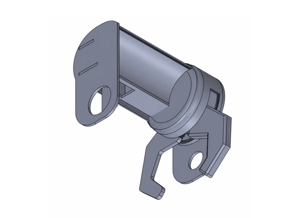
Overall CAD packaging
of the brake retrofit.
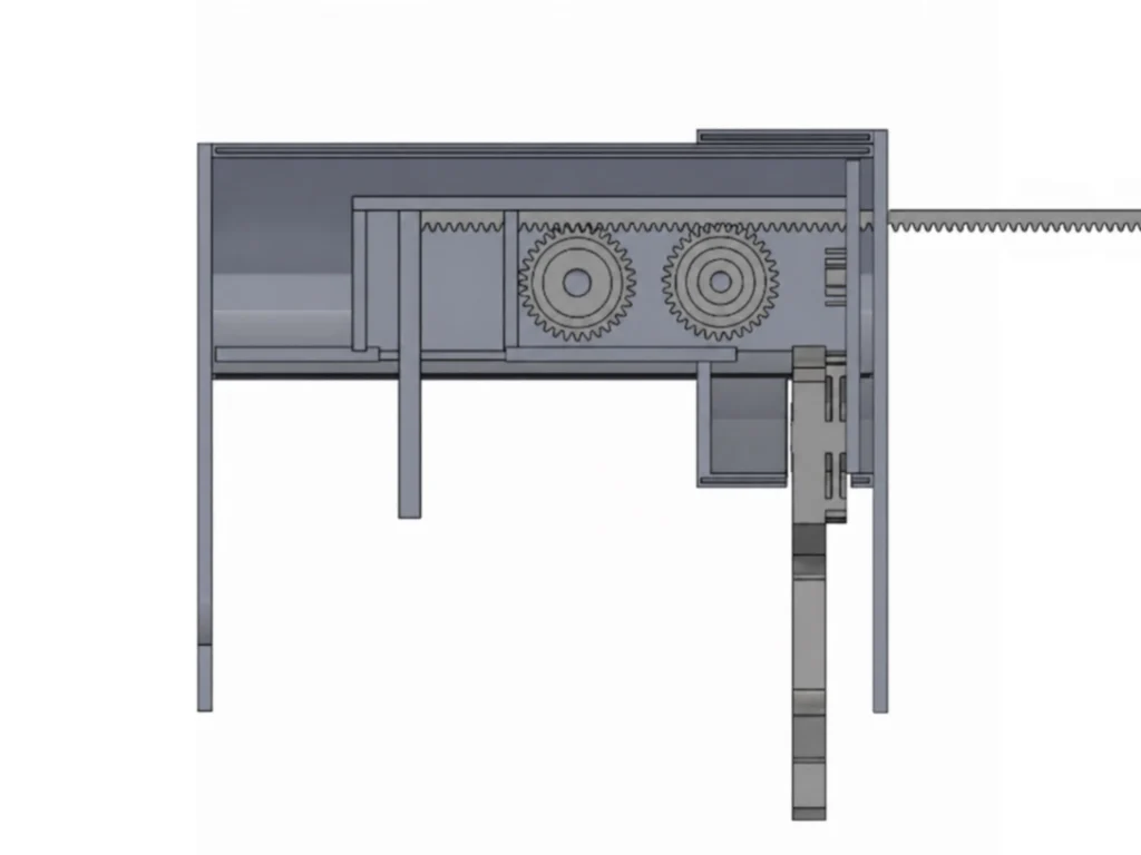
Internal arrangement of
the gears and claw actuators.
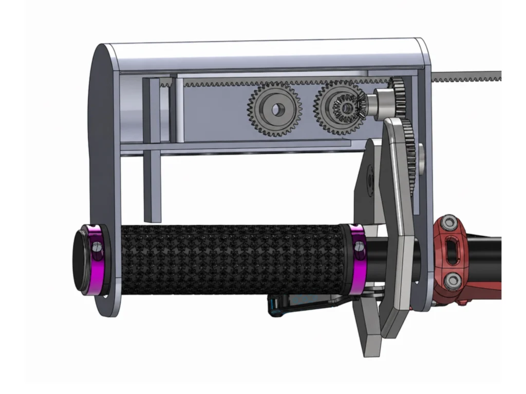
Retrofit integrated with the existing bicycle handlebar and brake.
Structural Analysis
Because the retrofit transfers braking loads through a new lever and housing structure, the design needed to be checked for stress and potential failure.
I modeled the brake lever as a simplified beam under a worst-case 5 N hand input. The analysis used force equilibrium to determine reaction forces, followed by shear-force and bending-moment calculations to identify the critical section.
The maximum bending moment occurred at the first housing contact, at approximately x = 3 inches, with a calculated value of 254 N·mm. Using the measured lever cross-section, the maximum bending stress was approximately 3.10 MPa.
Compared with an assumed mild-steel yield strength of approximately 250 MPa, the simplified model produced a factor of safety near 81, suggesting that bending of the lever itself was not the limiting failure mode.
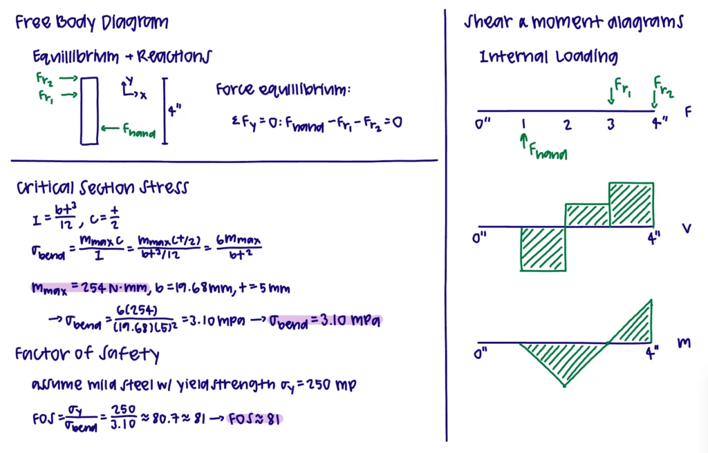
Hand calculations were used to trace the lever’s load path, identify the critical section, and
estimate a maximum bending stress of 3.10 MPa with a factor of safety of approximately 81.
FEA Validation
Finite element analysis extended the structural evaluation to components that were more difficult to represent with simple hand calculations.
The team focused on the internal cross-member supporting the lever and geartrain, along with one of the claw arms that transfers force to the original brake. Excessive deformation in either component could reduce brake engagement or disrupt gear alignment, making stiffness as important as material strength.
To evaluate a conservative failure case, the FEA model applied a total load of 100 N, considerably higher than the 5 N design input used in the analytical calculations.
The results supported the hand analysis. When scaled to expected use, stresses were in the same general range as the analytical result, while predicted deflections remained small enough to preserve brake engagement.
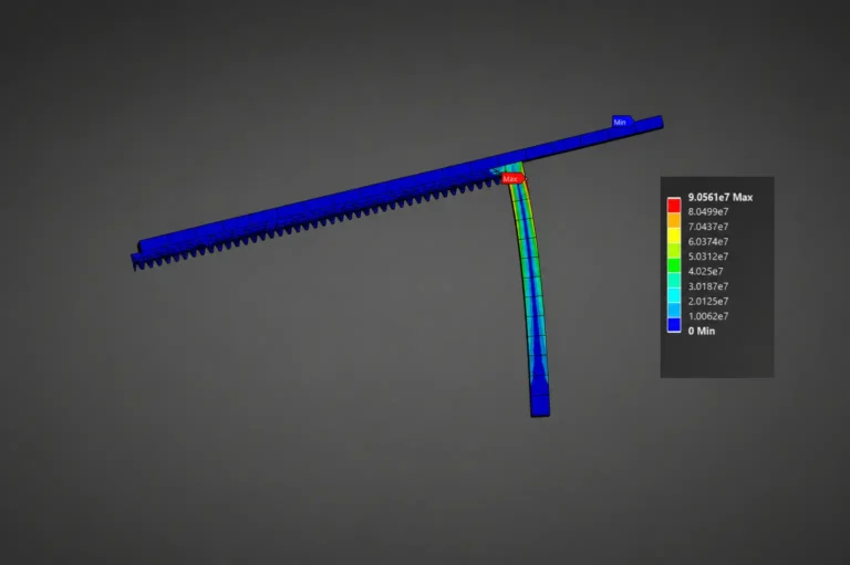
Cross-Member Stress
Stress distribution in the internal cross-
member under conservative loading.
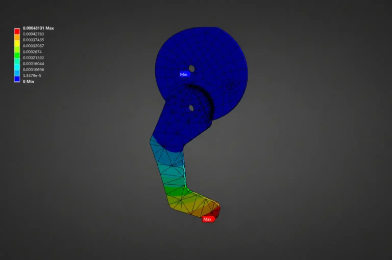
Claw Stress
Stress distribution in the claw actuator
responsible for engaging the original brake.
Prototype Development
The first physical prototype used 1/8-inch hardboard to evaluate fit, slot tolerances, shaft mounting, and gear meshing.
Hardboard was inexpensive and useful for quickly testing the basic assembly, but its thickness variation and rougher surface made it difficult to maintain the tight tolerances required by the geartrain.
The next prototype replaced the internal hardboard components with laser-cut acrylic and used a 3D-printed PLA housing. Acrylic provided a stronger, smoother, and more dimensionally consistent material, reducing friction and improving fit.
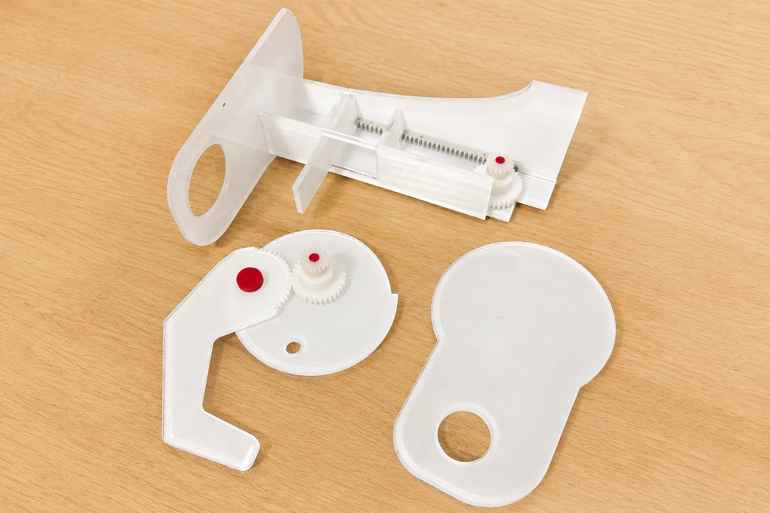
Laser-cut internal pieces and 3D-printed
housing components used to refine fit, alignment,
and assembly before final integration.
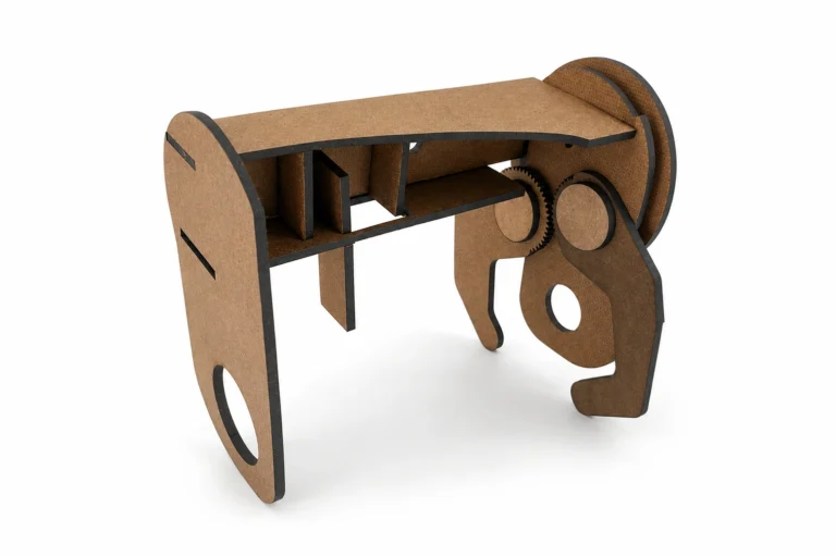
First Prototype
First hardboard prototype used to evaluate
tolerances, gear alignment, and shaft placement.
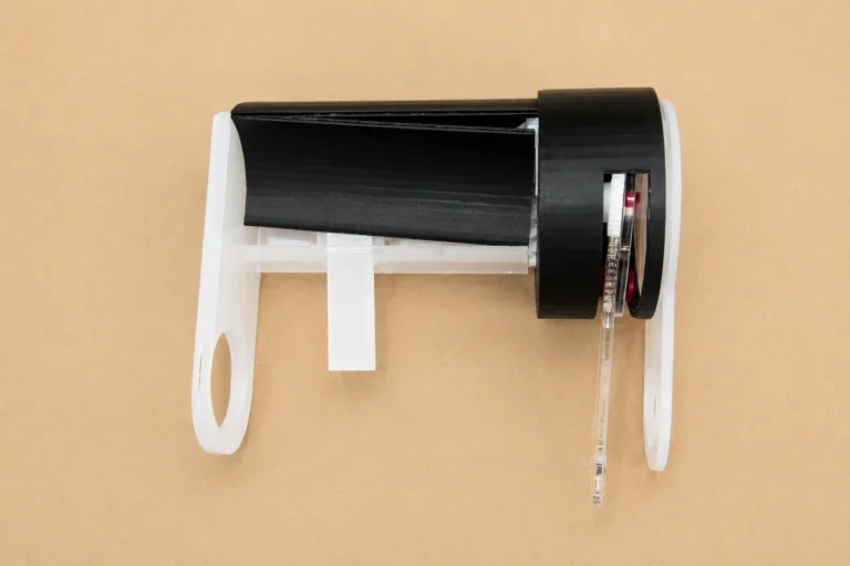
Revised Prototype
Revised prototype using acrylic internals and a
PLA housing to improve consistency, reduce
friction, and refine the mechanism.
Final Design
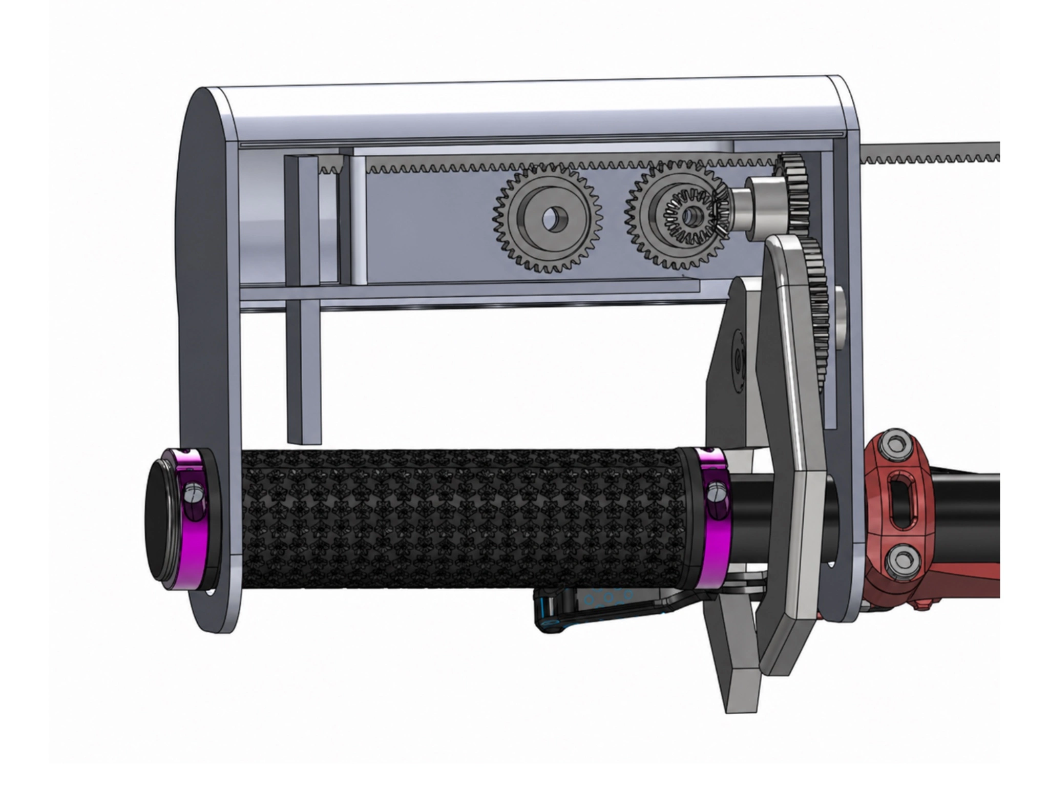
Final Take a Brake assembly integrating the horizontal push lever, internal geartrain, and claw actuators with the original bicycle brake.
The final Take a Brake concept combines a horizontal input lever, compact geartrain, structural housing, and claw actuator into a fully mechanical retrofit.
The system changes both the direction and magnitude of the rider’s input. Rather than relying on a strong finger squeeze, the rider uses a horizontal push that is amplified through the geartrain before actuating the existing bicycle brake.
The final concept achieved the intended mechanical architecture while remaining compatible with the original braking system and avoiding electrical components.
Results
The final design demonstrated that mechanical advantage and a redesigned input motion could address the limitations identified with conventional bicycle brakes.
The project achieved:
- a horizontal push instead of a traditional finger squeeze
- approximately 3:1 mechanical advantage
- an estimated reduction from 40 N to roughly 13 N of user input
- full mechanical operation without electronics
- integration with the existing bicycle braking mechanism
- analytical and FEA evaluation of critical load-bearing components
- physical prototypes used to identify friction, tolerance, and material issues
Future Improvements
Further development would focus primarily on validating the design with more representative users and refining the prototype for manufacturability.
- Expand testing with older adults and riders with clinically reduced grip strength.
- Use broader user data to refine the mechanical-advantage and ergonomic targets.
- Begin physical prototyping earlier to validate gear ratios and lever positioning.
- Incorporate material selection, manufacturing tolerances, and assembly considerations earlier in the design process.
- Improve documentation of testing and design decisions across iterations.
- Develop stronger production-ready internal components while maintaining a lightweight external housing.
Key Takeaways
Take a Brake showed me that accessibility sometimes requires redesigning the interaction itself rather than modifying an existing control.
The first rotated-handle concept reduced the required movement but still depended on finger strength. Moving to a gear-driven horizontal push addressed the underlying limitation more directly by changing both how the rider applies force and how that force is transmitted.
The project also strengthened my ability to move between different engineering tools. Hand calculations clarified the load path and critical stresses, FEA provided insight into more complex deformation and failure conditions, and physical prototypes revealed tolerance and friction issues that analytical models could not capture.
Most importantly, the project reinforced that usability and mechanical performance cannot be developed independently. The braking motion, gear ratio, structural stiffness, component alignment, material choice, and manufacturability all had to work together for the system to function reliably.